Author: admin

  • The Correct Anode Material for your Yacht

    The Correct Anode Material for your Yacht

    I’m not going to go into depth about the correct size, distribution and correct anode material for your yacht. The correct choice will depend on the hull material, salinity of water, berth location and quantity of submerged metallic equipment. There’s already plenty of information out there and I would recommend the website of MGDuff for the best guidance: http://MGDuff Catalogue

    This article gives an example of a recent problem of a 5-month old steel widebeam canal boat that was fitted from new with the wrong anode material. According to MGDuff: Use Zinc anodes in salt water, Aluminium anodes in salt & brackish water and Magnesium anodes in fresh water.

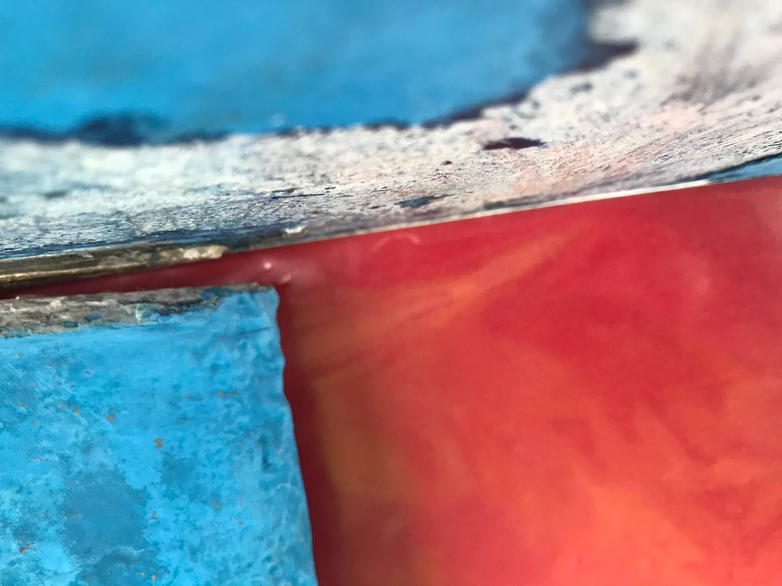
    The two following images were taken of a five-month old steel widebeam canal boat. From new she was launched into the brackish water of a coastal marina. Within the five month period, all of her Magnesium anodes had been consumed. As well as being the wrong material for brackish water, there were only four anodes for the entire vessel. Of primary concern was the condition of the hull paint. In the regions of the Magnesium anodes, the paint coatings had disappeared. The surfaces nearest to the anodes were bright, bare steel. As the distance from the anodes increased, the level of missing paint decreased. The missing paint around the Magnesium anodes occurs due to the caustic salts that build up in the surrounding water. These caustic salts are a by-product of the electrolytic decomposition of the over-reactive Magnesium. Note that in most areas, the exposed plating was shiny, bright and free of significant corrosion and free of pitting. This lack of corrosion could be attributed to the protection given by the anodes, but now that these were wasted, there was no longer any paint or anodes to protect the steel.
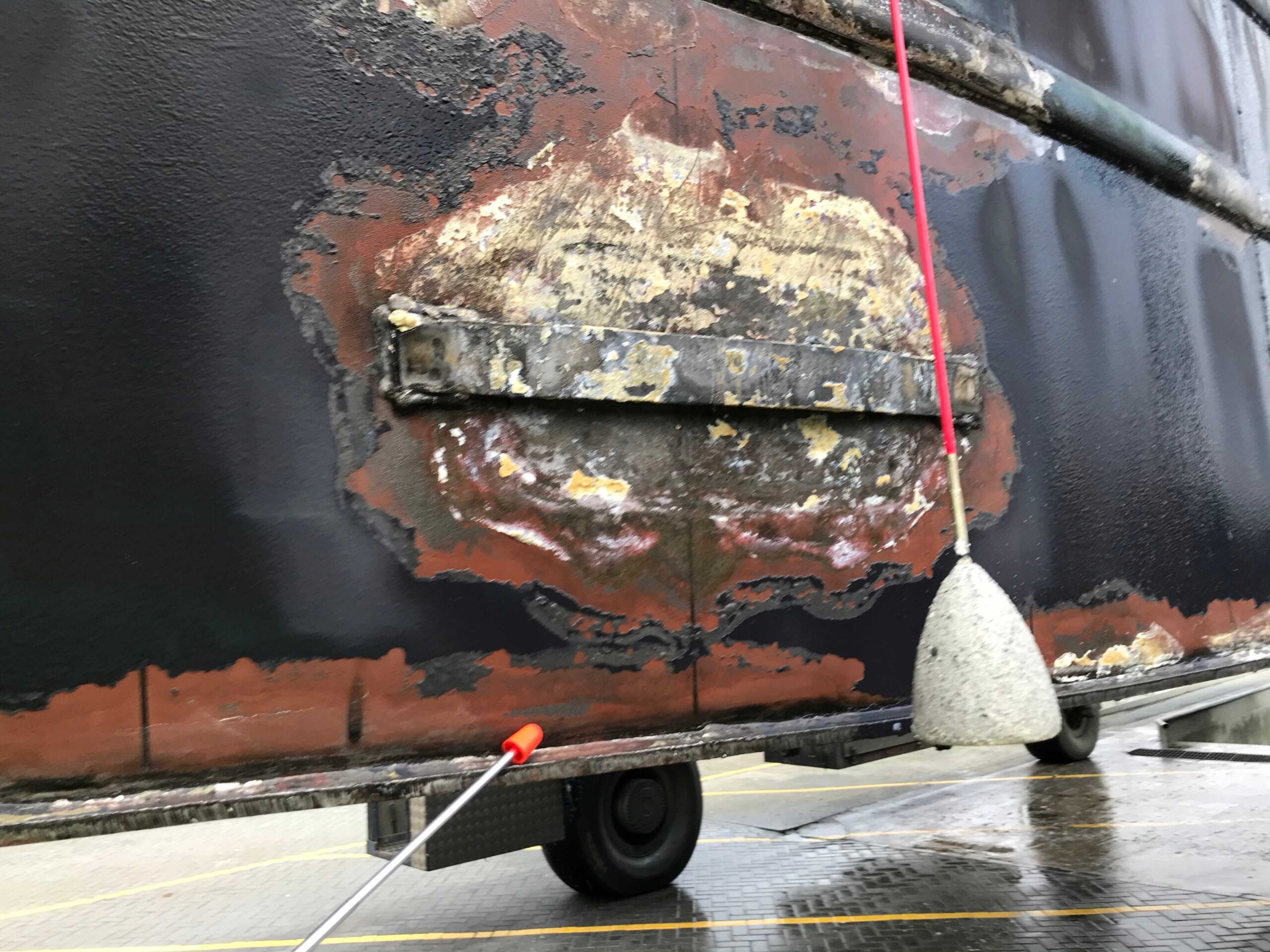
    The horizontal bar is all that remains of a 5 month old Magnesium anode on steel hull. Note missing paint

    In the image above, the conical-shaped object on the end of the red wire is an Aluminium hanging anode, installed by Fieldhouse Yacht Surveys as a temporary measure, to protect the bare metal until new Aluminium anodes could be fitted and the paint repaired.
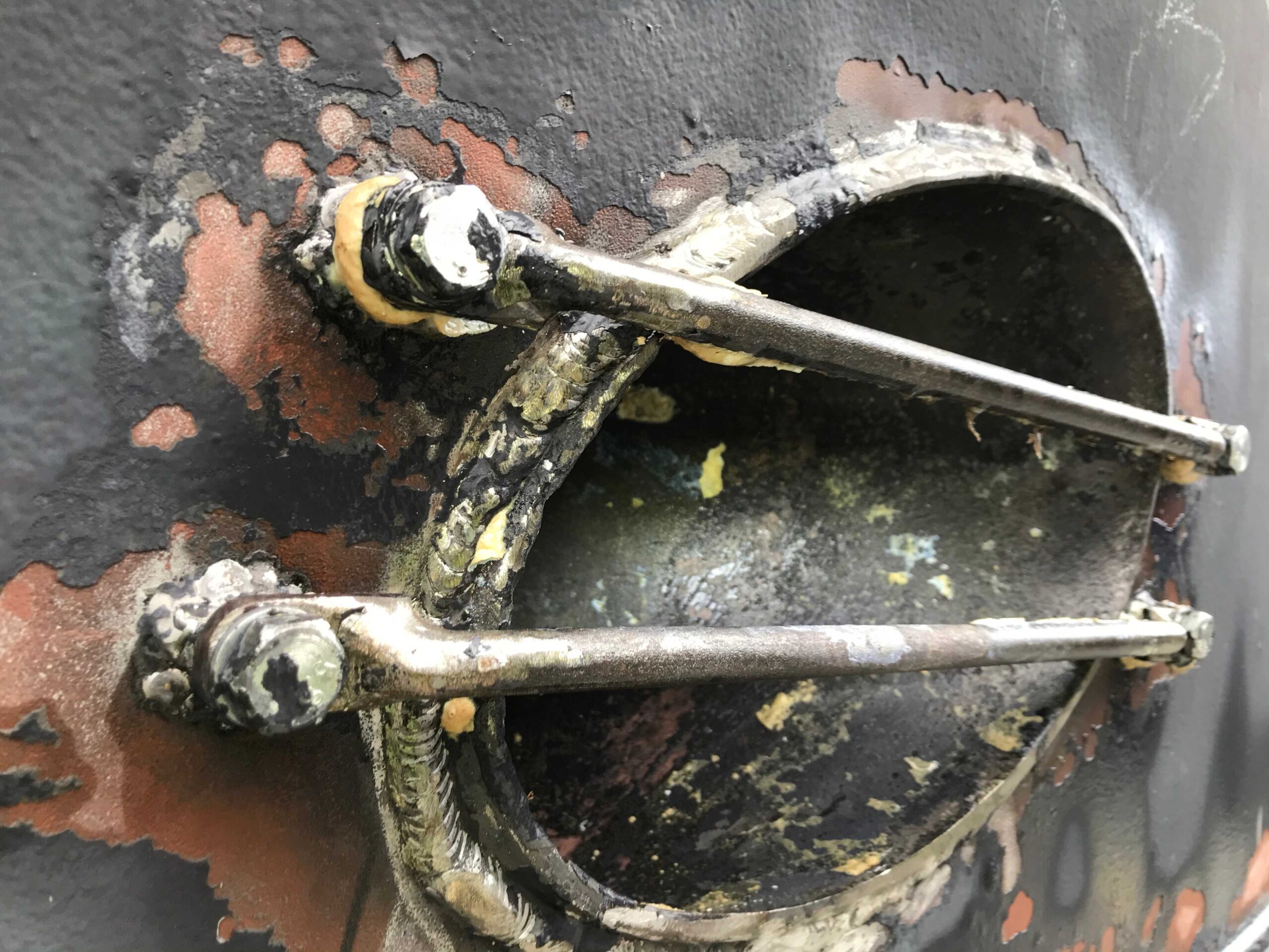
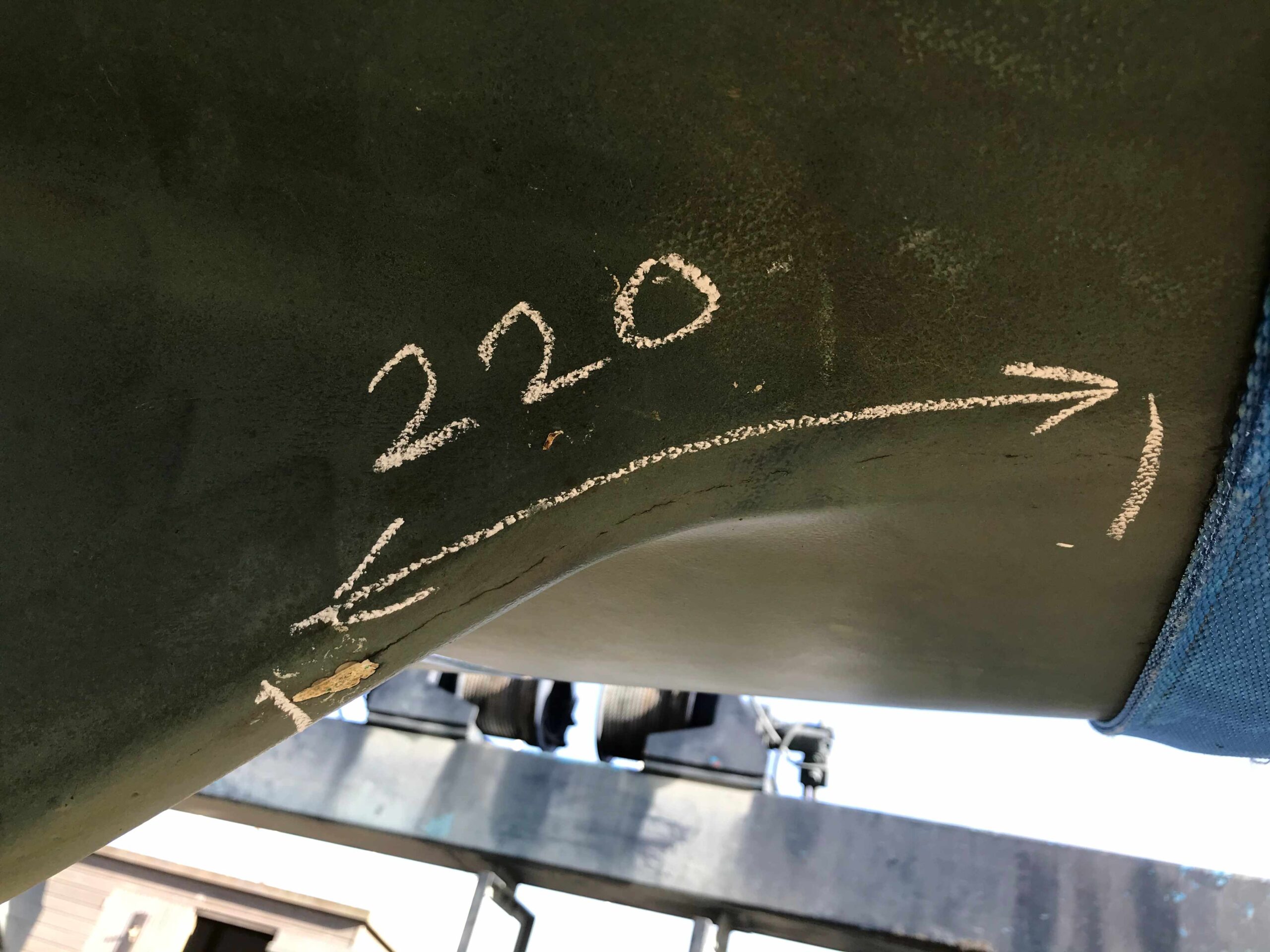
    Missing paint around bow thruster tunnel of 5 month old steel Widebeam

    The advice from Fieldhouse Yacht Surveys regarding the correct anode material was to replace all Magnesium anodes with Aluminium ones and to increase the quantity of anodes from two per side to five per side (ten hull anodes in total). Recommendations for the temporary application of paint were made, with a more thorough treatment in the Spring, when weather conditions were more suitable.

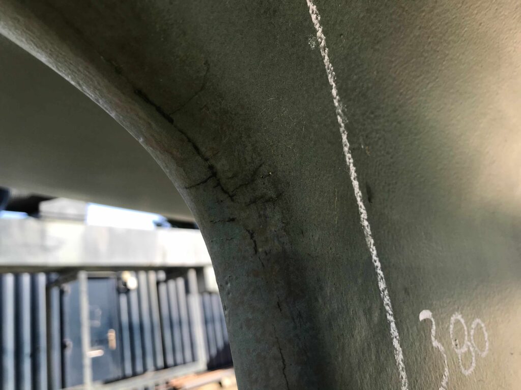
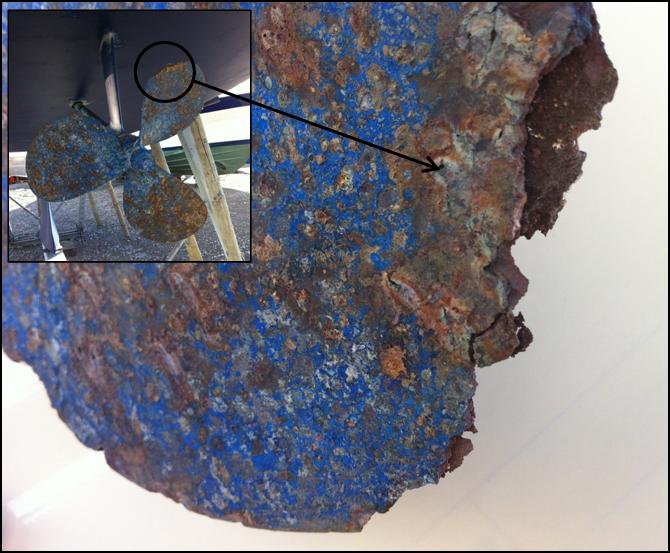
    The steel widebeam canal boat was lifted yesterday in order for the paint to be applied under the right conditions. The following images show that in the intervening 5 months, almost no paint has been removed from the hull. This means that the anodes haven’t created any caustic by-products that would remove the paint. Additionally, the Aluminium anodes have decayed to some extent, which shows that they are doing their job. I would be concerned if the anodes were free of decay. In brackish water, Zinc anodes of form a layer of Zinc Hydroxide on their surface. This indicates that they are not active enough, plus the coating of hydroxide salt reduces the effectiveness of the Zinc.
  • Tonnage Survey of Macwester 26

    Tonnage Survey of Macwester 26

    The initial enquiry from the Client for a tonnage survey on his Macwester 26 was received on 10th April. The survey was carried out three days later. By 16th April the application had been scrutinised & approved by IIMS and the certificate supplied to the Client. Everyone concerned deserves a gin & tonic for the quick turn-around of this application!

    Tonnage Surveys are required if a boat is to be registered under Part 1 of the British Registry of Shipping. The owner of the boat must be British and they must sign a Declaration of Eligibility and submit an application form along with proof of ownership.

    The calculated tonnage figure bears no relation to the vessels’s actual weight, but is a volume calculation based on the length times breadth times depth. The vessel may be in or out of the water whilst the survey is being carried out. Click on this link to find more information on the Tonnage Survey process.

    Tonnage Survey of Macwester 26 at Quay Lane Boatyard, Gosport
  • Damaged Keel Structure on 42′ GRP Sailing Yacht

    Damaged Keel Structure on 42′ GRP Sailing Yacht

    I was recently asked by a GRP repair specialist to investigate the gap in a hull-to-keel join of a 42′ GRP sailing yacht. The gap at the aft end of the damaged keel quite clearly indicated that part of the hull structure had failed, but the internal structure required closer examination in order to find the cause of the movement.

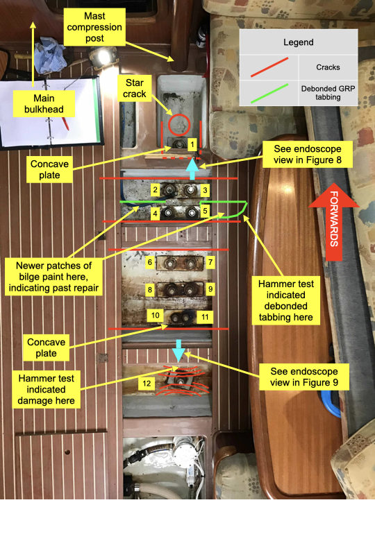
    Using a combination of visual inspection, hammer testing and endoscope examination, the areas of damage of the internal hull stiffening structure were found and recorded.

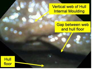
    Whether the boat was sitting with its weight on the keel or with the keel dangling in the air, it was not possible to see any movement or gaps appearing around any of the 12 stainless steel keel fastening studs or the surrounding hull structure. For health & safety reasons, I wasn’t able to sit inside the boat and observe what happened to the internal structure when the hoisted boat was lowered down onto its keel. I suspected that there was a gap between the hull and the GRP moulding of the internal stiffening structure. Movement of this gap would explain the 5 mm gap seen on the outside of the boat. This gap could have been found by cutting away part of the internal stiffening structure, but this was deemed to be a last resort. I inserted an endoscope into the ‘top hat’ section of the internal stiffening structure that was located nearest to the aft-most keel stud. Although the resolution was poor and the image looked more like something out of Monsters Of The Deep, or a lurid porn movie, it was clear that there was some sort of dark space or gap between the lower flange of the ‘top hat’ section and the hull.

    Not convinced? I wasn’t sure either, so I set the endoscope to record a video of the image and I got off the boat. The crew of the lifting hoist then lowered her back into her cradle. In this cradle, some of the boat’s weight is supported by four large steel supports, with the rest of the weight on the keel.

    Apologies for the quality of this video. It had to be severely shortened for me to upload it onto the website. To explain the video, you have to imagine that the endoscope lens is sitting on the floor of the hull. When the boat was lowered into the cradle, the keel pushed up the hull, which is seen in this video as the shiny upper bit moving downwards. The shiny bit is the vertical web of the ‘top hat’ section.

    The next step is for the GRP repair specialist to find the time in their busy schedule to remove the damaged keel and to repair the damage in the hull internal structure.

    Take a look at the following link for a copy of the survey report (names and locations changed): https://localtakeaway.co.uk/wp-content/uploads/2021/03/FYS_KEEL_DAMAGE_REPORT_issue_1.pdf

  • Insurance Survey of Swan 36 at Emsworth Yacht Harbour

    Insurance Survey of Swan 36 at Emsworth Yacht Harbour

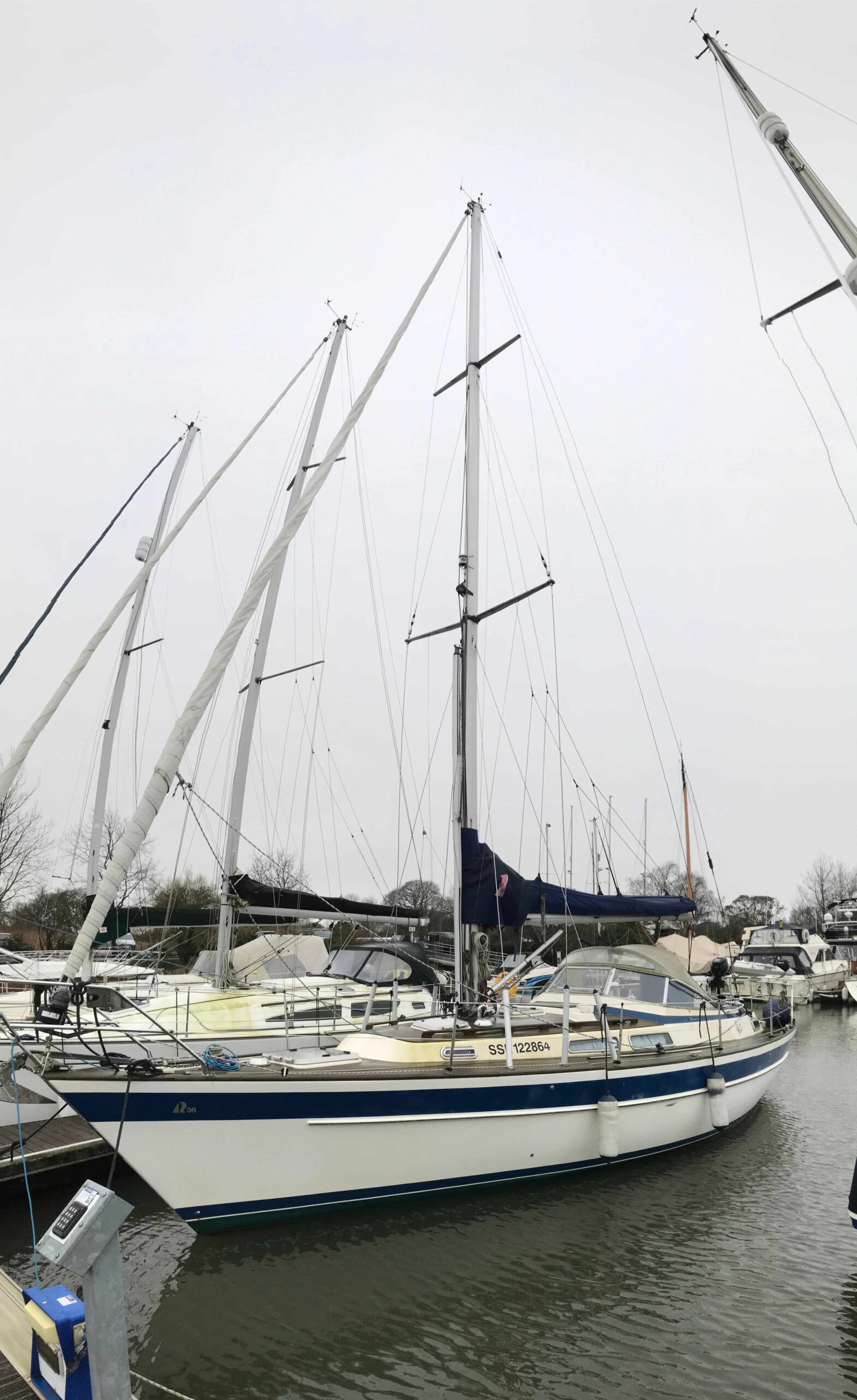
    Today’s survey took place with the vessel afloat and on her pontoon berth at Emsworth Yacht Harbour, Hampshire, UK. In a few weeks the boat will be lifted ashore for maintenance work. When she’s ashore I can continue with the rest of my survey, but t.oday’s inspection concentrated on the below-decks structure and systems.

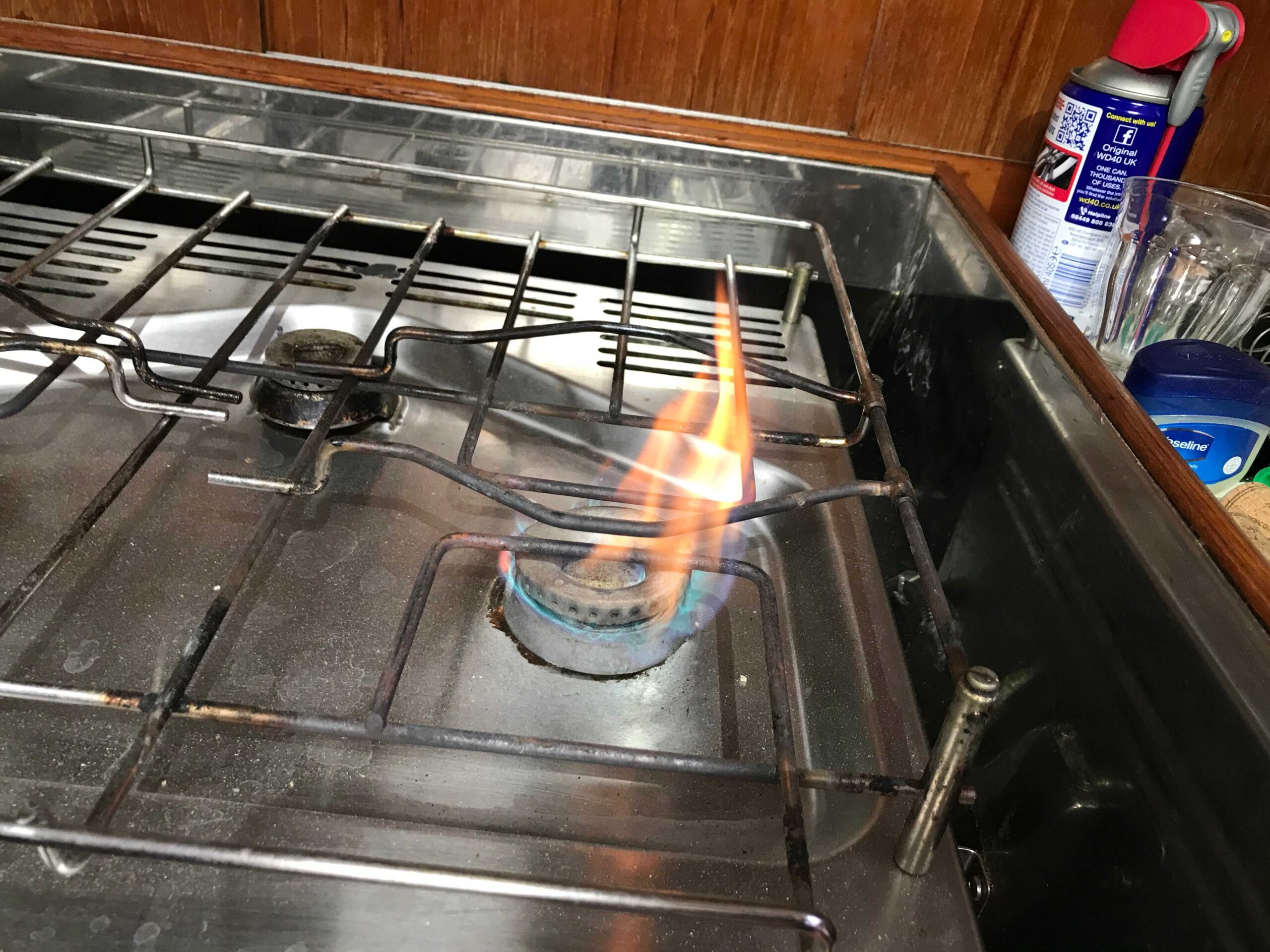
    This Swan 36 was designed by German Frers and built in 1989. She benefits from having been re-engined less than two years ago with a Volvo Penta D1-30F. Here inventory was mostly up-to-date, but as with most boats, there are always items that get neglected because they are thought to be serviceable. With a boat that is over 30 years old and has been well used, there will also be items that are wearing out and are due for replacement. For example, one of the flame heads on the galley cooker was distorted, giving a very poor flame pattern.

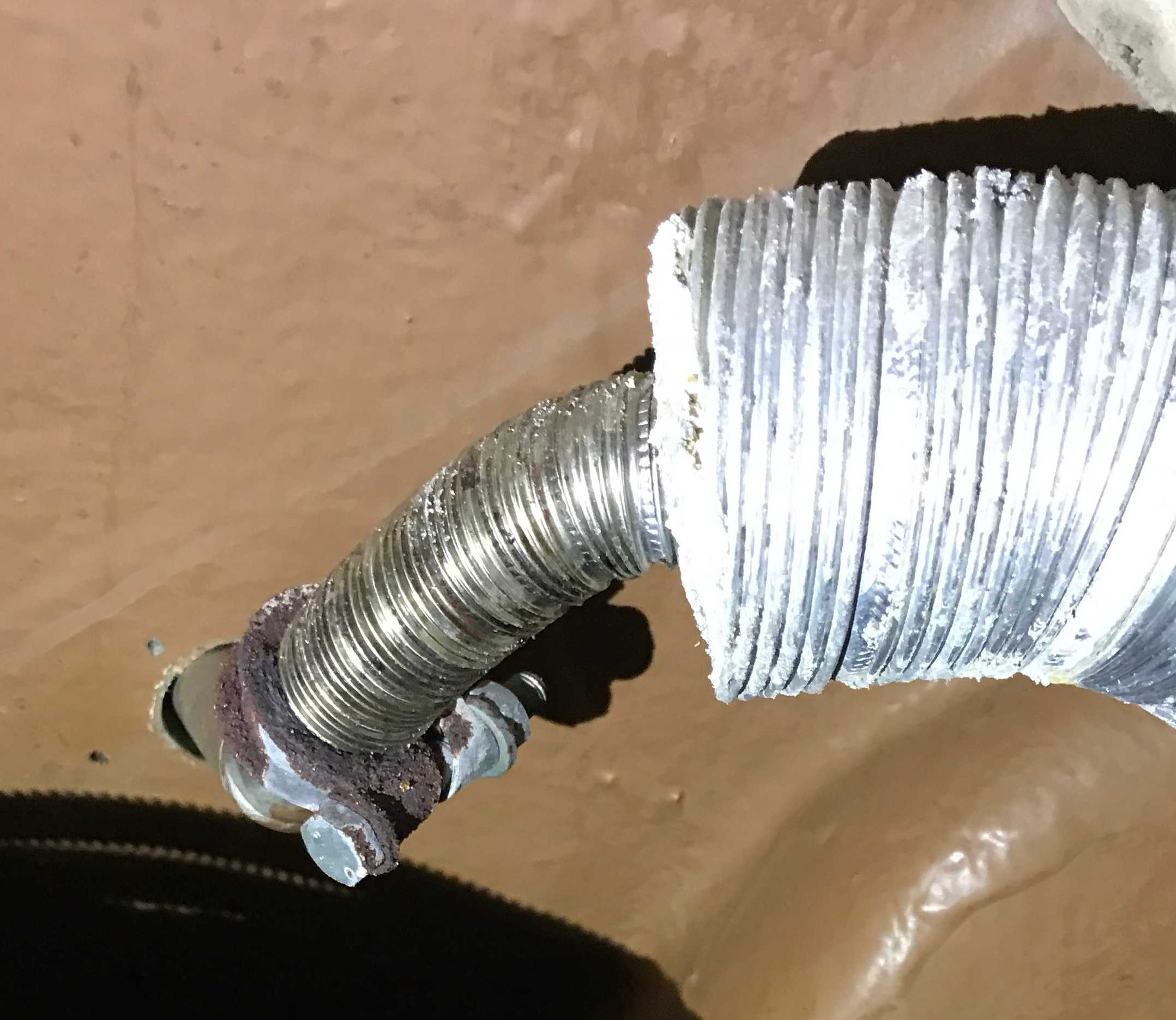
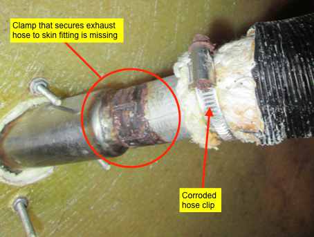
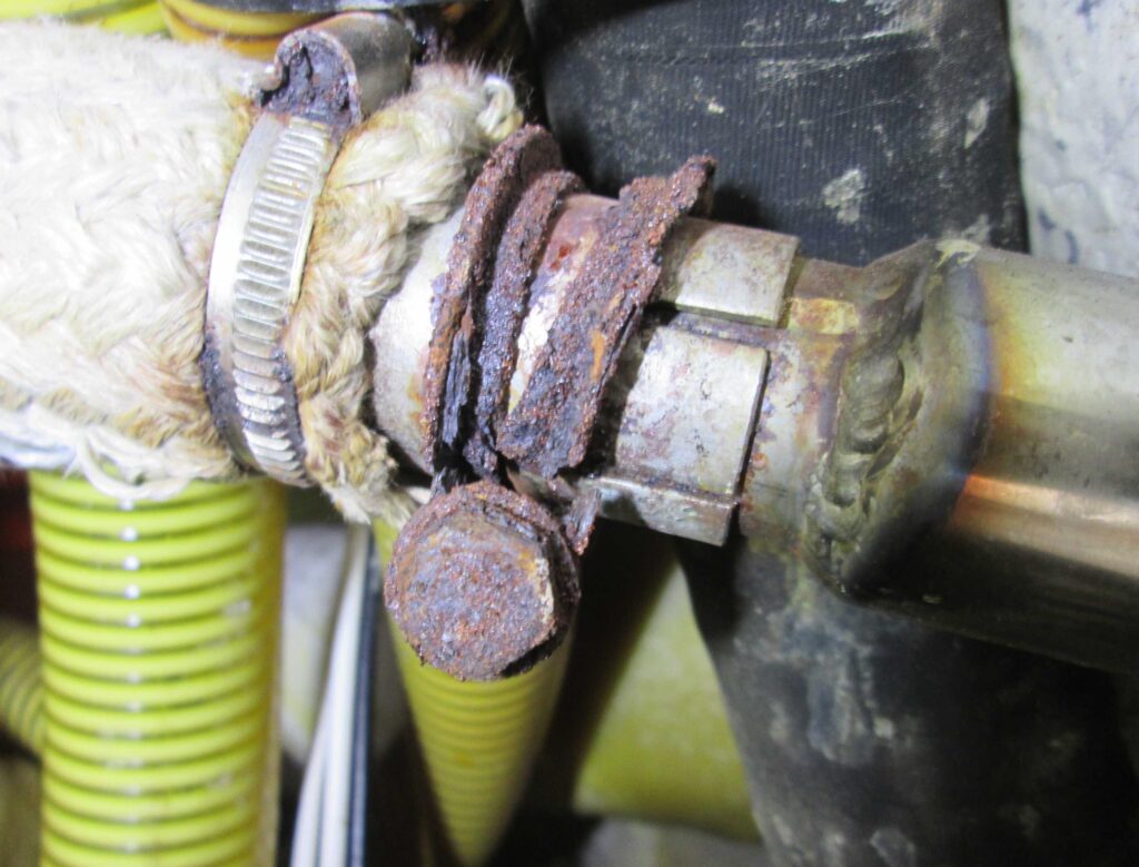
    Inspection of the Eberspächer diesel-powered space heater was difficult as the exhaust pipe was mounted high up inside the transom space, behind the aft cabin. This space was only accessible through a narrow hatch. The exhaust pipe of this heater was secured to the skin fitting with a rusty carbon steel clamp. These should always reconstructed from stainless steel. The stainless steel pipe was corroded too, indicating that it was overdue for replacement.

    Beneath the sole boards of the saloon and just aft of the keel supporting structure, one crack in the laminate was found to be extending aft from a limber hole. This crack extended into the laminate to a depth of 2 to 3 mm. Once the vessel is lifted ashore, I will be taking a close look at the underside of the hull in this region.

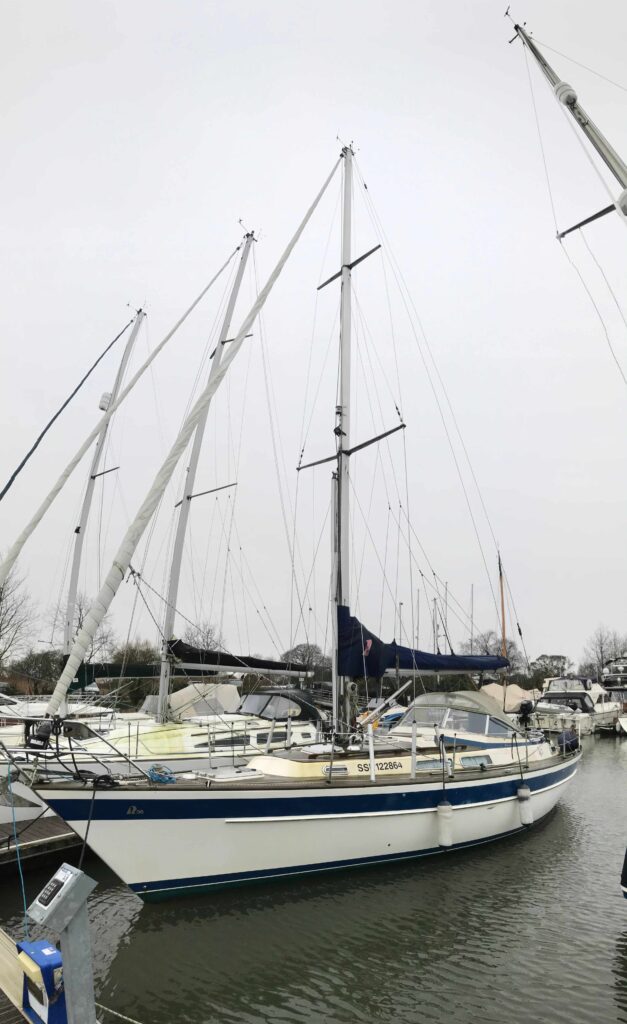
  • Pre-purchase Survey of 1990 Hallberg-Rassy-Rassy 36 Mk1 in Chichester Marina

    Pre-purchase Survey of 1990 Hallberg-Rassy-Rassy 36 Mk1 in Chichester Marina

    Day 1: Pre-purchase Survey with vessel afloat

    In order to inspect a vessel of this size with the appropriate level of detail required for a pre-purchase survey, this boat was inspected over a two day period. The first day was spent with the vessel afloat, tied to her pontoon berth at Chichester Marina.

    This boat had spent time cruising the Thames Estuary and the East Coast, so I was looking carefully for evidence of grounding damage (although any surveyor should always be looking for signs of this). The lead keel wouldn’t necessarily show evidence of grounding as any dents could have been be hammered back into shape and faired. The internal stiffening structure beneath the sole can suffer badly in the event of a grounding. The top hat sections of the stiffening structure can become debonded from the hull and extensive repair work can be required in order to return the strength and stiffness to the hull.

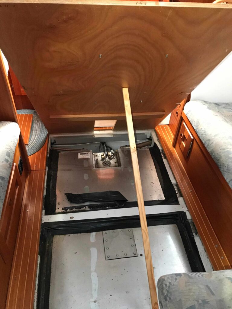
    My survey commenced at the very forward end of the forepeak, working my way aft. All bunk covers, locker covers and sole boards were lifted in order to get the best possible access to the inside of the hull. In order to get beneath the large central sole board of the Hallberg-Rassy-Rassy 36 Mk1, the board has to be unscrewed and then lifted, together with the bolted-down dining table.

    The two massive fuel tanks beneath the saloon sole didn’t provide much direct visual access, so the keel fasteners and adjacent hull structure had to be inspected with an endoscope. Not as ideal as direct visual access, but enough detail to see the good state of a number of the the studs and nuts.

    The rest of the first day was spent working my way through the inside of the boat, ending the day deep inside the large cockpit locker. I had also performed a visual inspection of the engine & transmission, but the engine test in the harbour was going to have to wait until the second day of the survey.

    Day 2: Pre-purchase Survey with vessel ashore, followed by sea trial

    As anticipated before the survey, there was a higher possibility that the vessel may have suffered grounding damage as it was know that she had spent some time cruising the Thames Estuary and the East Coast. Detailed examination of the hull interior found no evidence of this: All bulkheads were free of damage and their connections to the hull and deck mouldings were free of movement, cracks or delamination. The substantial hull stiffening structure around the keel & beneath the mast compression post, was also found to be free of debonding, cracks or other damage.

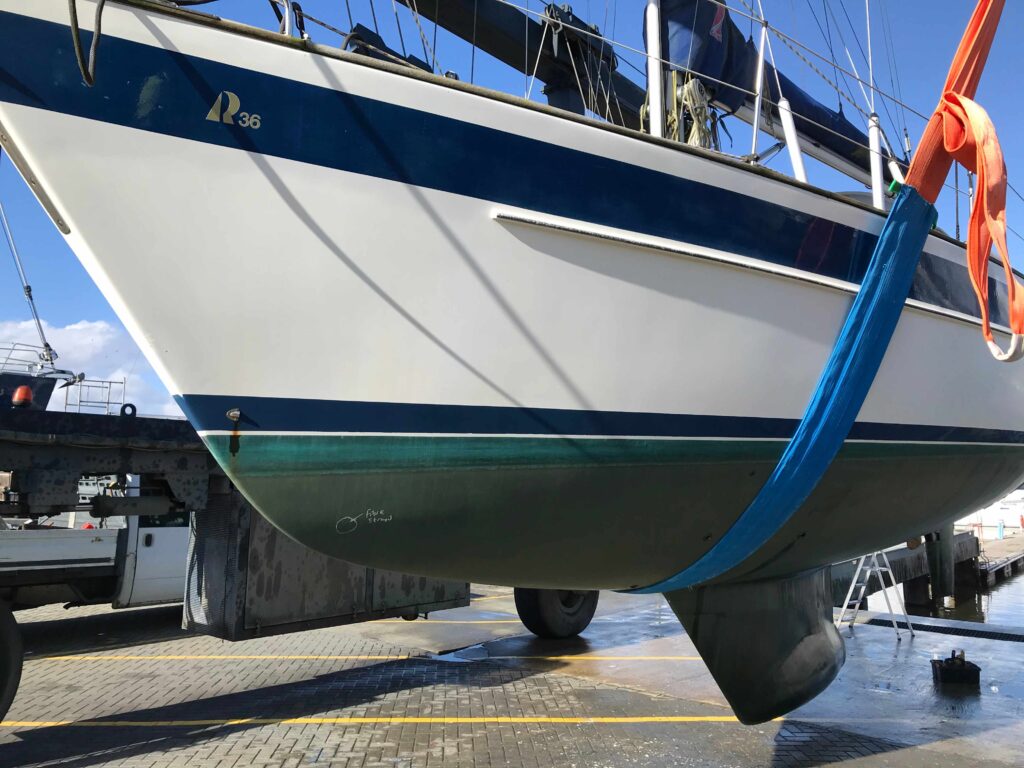
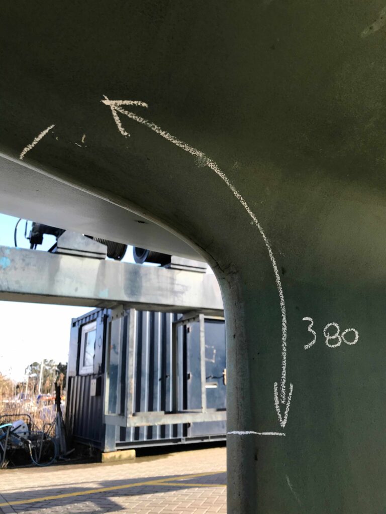
    Once the boat had been lifted ashore,  evidence of minor grounding was found at the fore & aft ends of the keel. The base of the lead keel had various scrapes and gouges from 30 years of cruising. There were no significant dents at the forward, lower corner, but some touched-up paint indicated that a repair to this region may have been carried out since the original coating had been applied.

    Once the boat was back in the water, it was straight out into the harbour to test the Volvo Penta MD2020 Diesel engine. It’s really important to get the engine up to full working temperature and to assess the engine at various speeds whilst under load. The close, but not too close inspection of the engine & transmission (with ear defenders) found excessive levels of vibration, most notably at the output shaft. Earlier crowbar testing of the engine mounts had revealed that these were old but intact. The out-of-water inspection had found that the propeller shaft was straight. There was some vertical wear in the cutlass bearing, but almost none in the lateral direction. Whilst the boat was ashore, I had also noted some gel-coat cracking around the area where the bronze stern bearing was attached to the hull. This evidence lead me to conclude that the most likely cause of the excessive engine vibration was the aged engine mounts. It is likely that the rubber has also distorted over time, leading to the dropping of the engine, shaft misalignment, increased vibration and uneven wear of the cutlass bearing.


  • Flooded Yacht: Damage Survey

    Flooded Yacht: Damage Survey

    I was recently asked to undertake a Damage Survey of a flooded yacht. My instruction from the Insurance Company was to inspect and assess the nature, extent and cause of the damage to the vessel.

    Water had entered the vessel over a period of time, leaving the boat low in the water and the engine partially submerged.

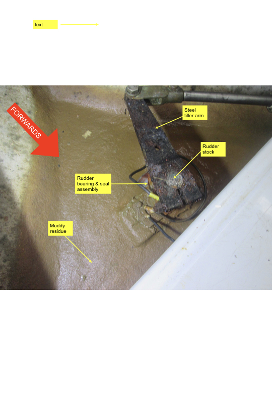
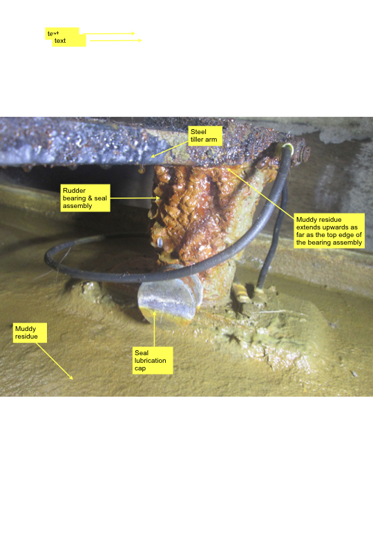
    She was inspected out of the water at East Cowes, Isle of Wight. In my search for the cause of the leak and working my way from bow to stern, I found water and muddy residue around the upper bearing & seal of the rudder assembly. This provided good evidence that water had leaked into the vessel from the top of the bearing assembly. At this stage of the inspection, I could have packed up, gone back to my office and simply reported that the rudder bearing & seal assembly was the most likely origin of the leak. This conclusion would have been unsatisfactory as it would have required the re-floating of the vessel in order to test & confirm that the rudder bearing & seal assembly was leaking. This task would have involved significant additional costs, which would have to be borne by the Insurance Company or the Insured.

    In order to confirm that water had leaked around the seal of the rudder bearing, I built a dam around the bearing assembly, which was then fed with water from a hose. I then went outside to check for water. The YouTube video shows the test.

    The result of this test confirmed that the faulty or worn water seal of the rudder bearing was the proximate cause of the water ingress. The head of pressure on the bearing seal from this water test was approximately 2 to 5 cm, which was considered to be very low. The rate of water leaking was estimated to be at least 3 to 4 drops per second. When the vessel was originally afloat, the pressure head would have been approximately 20 cm, which would have created a flooding rate that would have been approximately 4 to 10 times greater than the leakage rate seen during this test, although this rate would have been reduced due to the accumulation of mud inside the rudder bearing & seal assembly.

    If you have any questions regarding this Damage Survey, please leave a comment or contact us via our website.

  • Yacht Insurance Survey

    Yacht Insurance Survey

    A Yacht Insurance Survey may be required by your Insurance Company. If your Insurance Company has made it a condition of cover, Fieldhouse Yacht Surveys and Consulting Ltd can undertake the Insurance Survey for you.

    Our reports are accepted by all of the marine insurance underwriters.

    The Insurance Survey report will be acceptable to your Insurance Company. In addition to this, the document will contain recommendations relating to defects or equipment deterioration that would affect the vessel’s or crew’s safety. Each recommendation will state whether the defect should be rectified immediately or within a set period of time.

    Press here to view a number of our sample reports

    Contact us via this link or telephone us on +44 (0)7411 740 789 to discuss your specific requirements.

  • Insurance Survey of Etap 32i

    Insurance Survey of Etap 32i

    I have nearly completed the Insurance Survey report for the inspection of this Etap 32i. These boats were designed by Philippe Harlé & Alain Mortain and built by Etap Yachting of Belgium. About 150 were built between 1992 and 2000, making this 32i one of the earlier ones.

    They have double-skinned hulls, with the majority of the voids filled with closed-cell polyurethane foam. Etap claim that this makes the boats unsinkable, but also like to point out that the foam improves sound & heat insulation and adds to the stiffness of the hull too. This particular yacht has been very well maintained by her first and only Owner. Approximately three years ago I managed the partial re-fit of this boat, which included the overhaul of many bits of equipment, including the replacement of all of the below-water skin fittings & valves with ones made from glass-reinforced nylon by Forespar. Yesterday’s survey of the boat was fairly uneventful, but the lack of hose connections to the vessel’s only manual bilge pump was a surprise. If the boat was flooded during an incident, the built-in buoyancy might prevent it from sinking, but would their insurance policy cover them if the pump was known to be poorly maintained?

  • Insurance Survey of Princess 45

    Insurance Survey of Princess 45

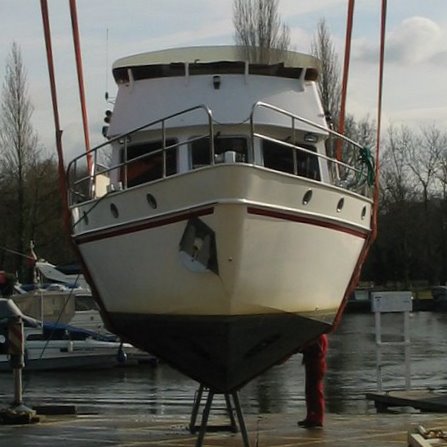
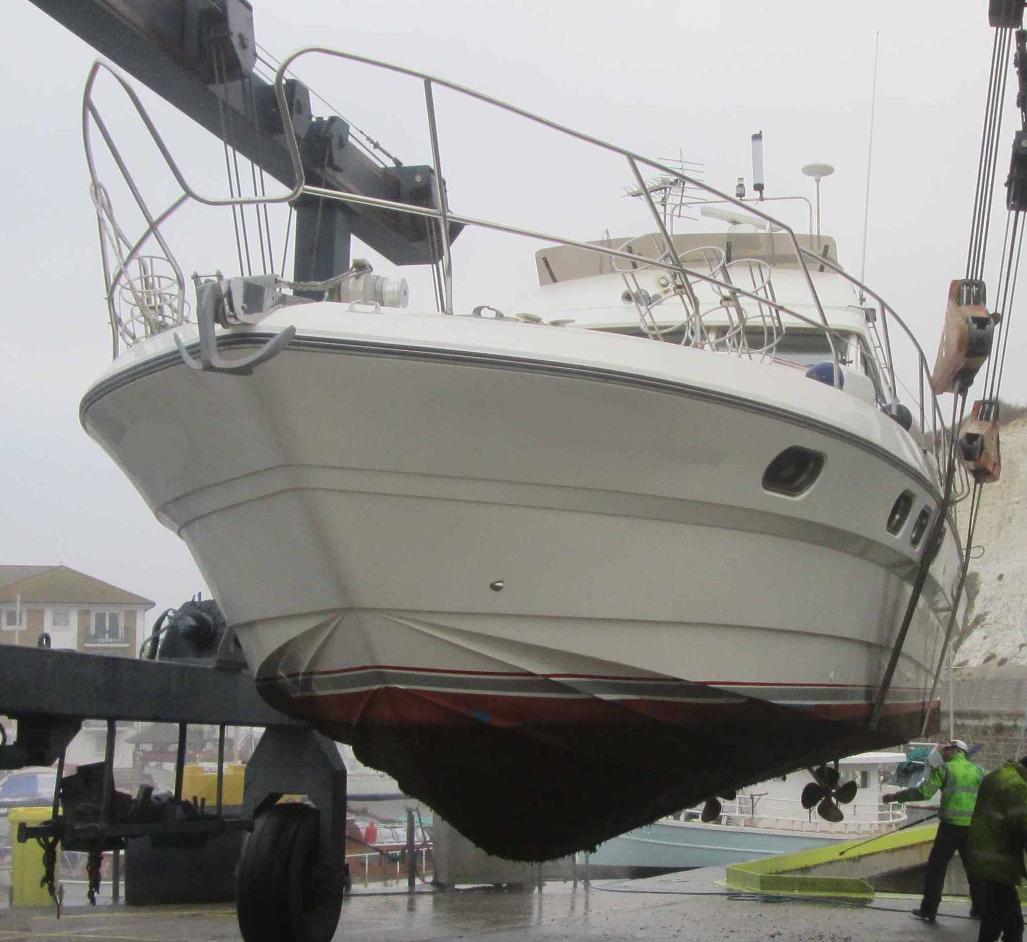
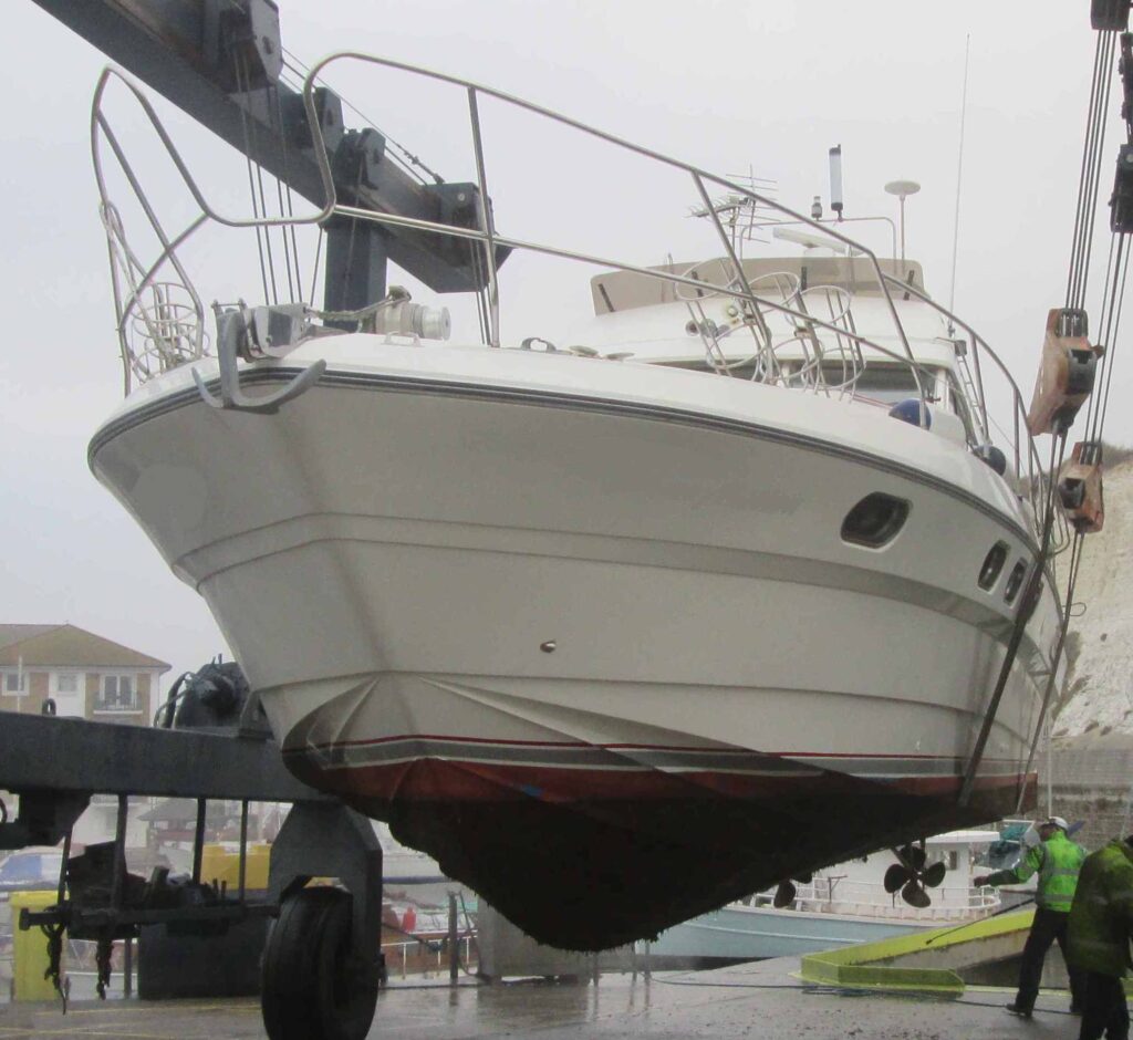
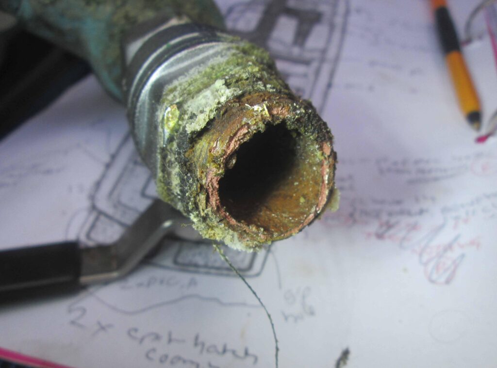
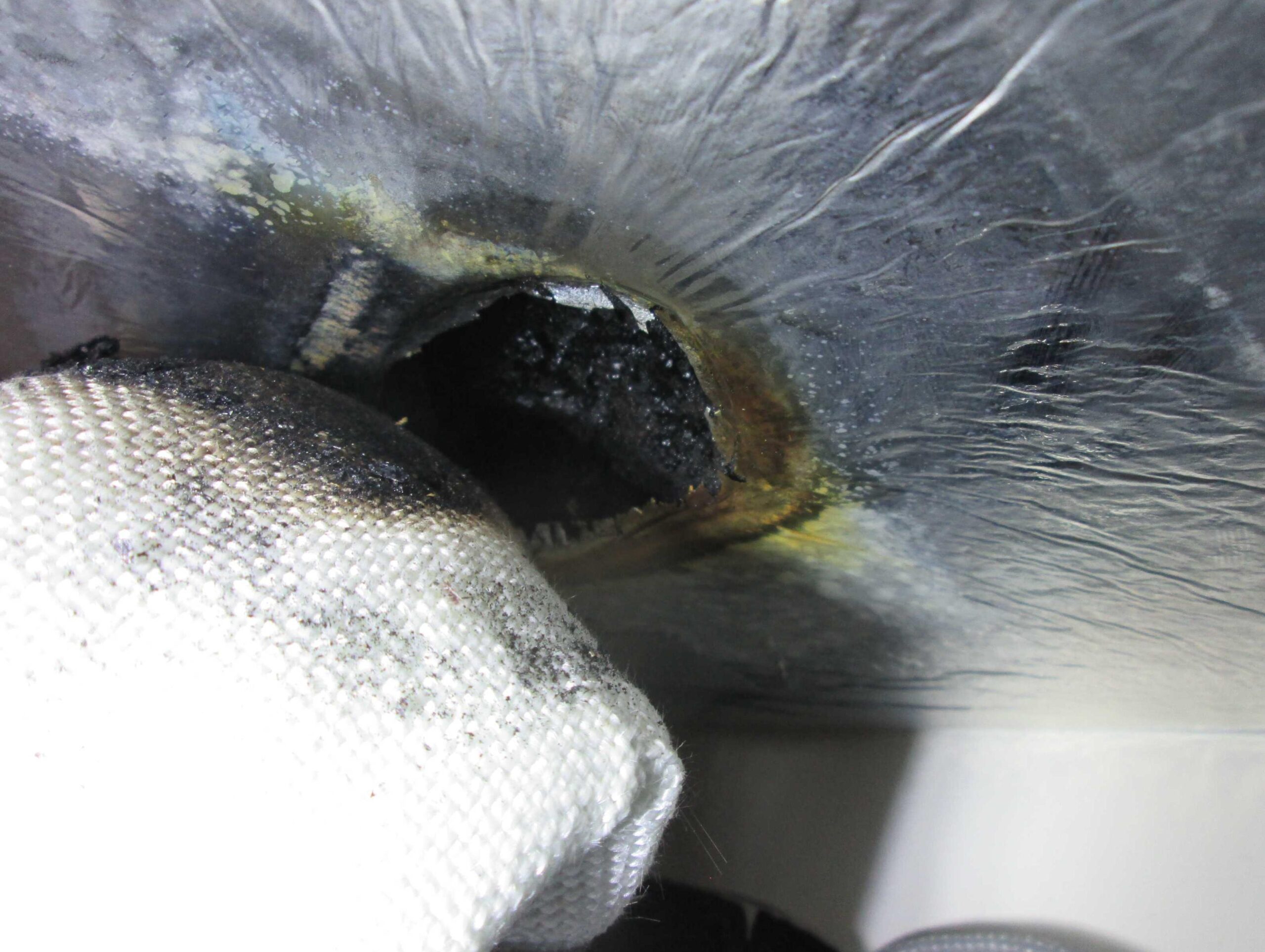
    After a few delays with the lifting hoist, this Princess 45 Flybridge Cruiser was safely lifted for the inspection of the underwater parts of the hull & propulsion equipment. Once it was found that all hull anodes were in need of replacement, it was decided that she would remain ashore for the next few days. This was quite fortunate for me because the subsequent testing of the through-hull valves resulted in the fracture of one of the underwater fittings. If the vessel had been afloat, this find would have at least given me a partial soaking. I always keep a range of softwood bungs in my toolbag for such an eventuality.

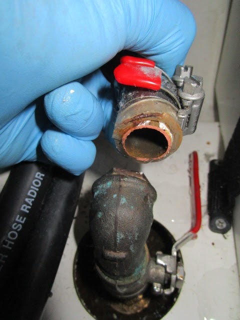
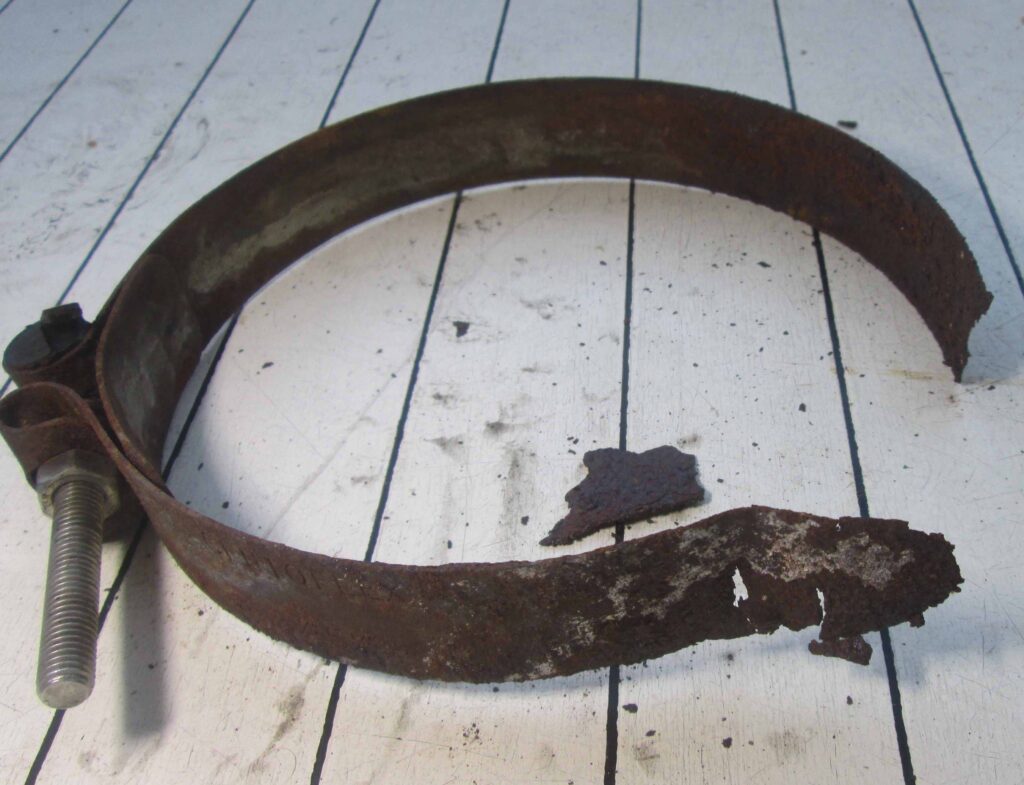
    It’s not just the underwater parts of the boat that suffer from corrosion. Even in the relatively dry atmosphere of the engine compartment, metallic parts will still corrode, particularly if they are made from mild steel. The corroded exhaust hose clamp shown below was one of a pair that secured a length of exhaust hose to the exhaust elbow of the starboard engine. Not particularly unusual for an engine of this age, but to leave these hose clamps to decay and fail, even after a fairly recent engine service, is leaving the engines at risk of failure.


  • Safe Installation of Diesel Heaters on Yachts

    Safe Installation of Diesel Heaters on Yachts

    There’s a wide choice of good quality diesel-powered space heaters these days, but in my surveys, I often find that the problem lies with the quality of the installation of the heater units. The positioning and securing of the lagged exhaust pipes is not always up to standard: Poor quality pipe clamps, missing pipe clamps (or maybe they corroded and fell off) and lagged pipes positioned too close to compartment insulation or GRP mouldings. The attached photos show just some of the nasties that I have found in cockpit lockers and engine compartments. The photo of the missing clamp was taken shortly after the unit had been serviced by an authorised agent. If I hadn’t found this defect during the survey of the vessel, the boat may well have sailed for another ten years without the Owner being aware that his heater was poorly installed and in an un-safe condition.

    Maybe the manufacturers of these products could take an idea from the Defence & Aerospace Industry: Where threaded fasteners are used to secure an item, these are often of the ‘captive’ variety. This means that when the screw is un-fastened, it won’t fall out and disappear inside the aircraft, submarine, or in the case of boat heaters, into the bottom of a wet, dark bilge. Judging by the quality of some of the non-stainless steel hose clamps that I have seen on heater exhaust pipes, I can only assume that the Fitter has lost the original pipe clamp in the vessel’s bilge, or in the back of his van, and has simply fitted an inferior equivalent clamp. If the original clamps were integral to the heater unit and the skin fitting, there would be no chance of these crucial items going missing and this would reduce the likelihood of poor quality clamps being used in their place. These would cost more to manufacture, but it would be justifiable in passing this cost on to the consumer as the durability and security of these clamps is of significant importance when ensuring that the heater units remain safe throughout their life.

    Whether my survey inspection finds the diesel heater unit to be well installed or poorly installed, I always recommend that the vessel is fitted with one or two Carbon Monoxide alarms. These units are a potential life saver, but they are no substitute for a correctly installed and well maintained fuel-burning heater unit.